Making
Double-Acting Bellows for the John Smith
Organs
The main purpose of this article is to demonstrate how easy it is to make
double-acting bellows to my new design (shown on this
page). But rather than build a useless demonstration version, I decided
to build a version that could be put to use afterwards. So I made these
bellows with dimensions compatible with the Busker plans. They are
11.5" long and 7" wide. A larger version could just as easily be made
for the Universal organ. In each case they will supply more than double
the amount of wind. They are unashamedly made from 1/2" thick MDF.
MDF is perfect for making bellows as it is strong, doesn't warp or
split, and accepts holes with perfect edges. It does need sealing well
though. 1/2" thick MDF is used to provide a large gluing area for the
leather around the edges, but thinner could be used if extra thickness is
provided by battens around the edges.
I deliberately made these bellows as three separate units, to show how easy
they are for a beginner to make. However, some economies can be made if the
units are combined together, and then covered as a whole unit. For instance
two of the boards could be replaced by glueing battens around one of the
other boards. You can decide for yourself exactly how you want to make
it. In case of difficulty, refer to the Busker plans, as the construction
techniques are exactly the same as the ones in the plans. In fact these are
easier to make than the ones in the plans, where the reservoir floor is formed
from the top of the two bellows and a sealing strip.
See also my separate article on how to make and cover
bellows
There is a MK2 version of these bellows which provides
a slightly more stable supply
|
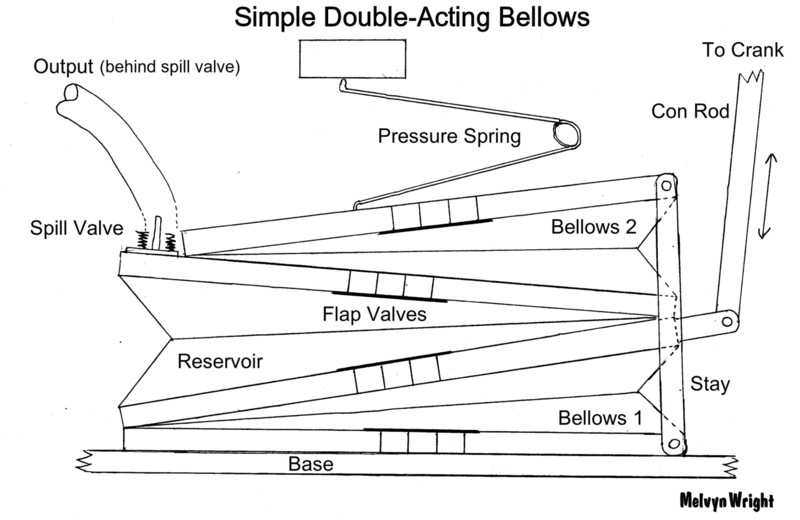
Diagram of the finished double-acting pump |
| Making the Bellows |
 |
 |
| Left: Cut out the six boards from ½" thick MDF:
Bellows1 top and bottom and Reservoir top and bottom are all 11.5" x 7".
Bellows2 top and bottom are 9.5" x 7". Label the boards at the top left to
prevent them getting mixed up, or disorientated. This is essential
otherwise you will get hopelessly confused!.
Right: Cut out the centre of two of the Bellows boards (Bellows 1
top and Bellows 2 bottom) leaving a square framework. A jigsaw or scroll
saw is suitable for this job. Alternatively, these two boards can be
replaced by battens forming a rectangle, but I found it easier, quicker,
and stronger to make the framework from solid MDF. (MDF is cheap!) The
centre cut-outs can always be used to make other parts. The purpose
of these is to clear the flap valves in the adjoining boards.
|
 |
 |
| Left: Drill six holes (not four as shown) in each of
the solid boards with a 20mm flat bit. The position of these holes
is not important, I put them in the centre. Drill from each side of
the MDF to avoid splintering and breakout of the surface. Sand flat.
Right: Fit the four leather flap valves in the four solid boards.
See the diagram at the top for where they fit. Notice that two of them go
above the board, and two go below the board. I used leather strips
1.5" wide. Lay the strip over the holes and glue it at both ends.
|
 |
 |
| Left: Take the top reservoir board and drill a large
hole with a flat bit, (suggest 25mm) to take the air supply tube to the pressure
box. Alongside this hole, cut out a square hole 25 x 40mm for the spill valve.
Both of these holes must be close to the front edge of the board, outside
the area of the top bellows and opposite the hinge. I put them on a
1" centre line from the edge.
Make the spill valve (see my article for making a
suitable spill valve) but do not fix it on permanently yet. The
bellows will be much easier to cover if the spill valve is not fitted. Because
of the movement of the reservoir, the spill valve is operated by a length
of cord rather than a fixed stop, so make sure that the operating lever is
long enough to extend over the side of the reservoir.
Right: Make and fit the connecting rod to the front of the bellows.
Screwing into the edge of MDF may not provide a strong enough connection
for the connecting rod, so take a piece of hardwood and glue it into position
inside the front edge of Bellows 1 top. It is important that this piece
of wood does not protrude above the surface of the MDF as that would cause
leaks when the board is later glued to the reservoir. When dry, drill
a pilot hole and fix the pivot to the bellows with a No.8 screw. When satisfied
with the fit, remove it again as it will make the bellows easier to cover.
Depending upon your crankshaft, you may wish to move the pivot along
to coincide with the horizontal position of the crank. Realise that you can
still get full access to the back of this connection after the bellows have
been covered.
|
 |
 |
The three spacers added at the hinge ends |
The leather hinges glued on |
| Set your bandsaw or table saw to ½" in preparation for
cutting lots of ½" strips from 3mm MDF. You will need around 15 feet
of this to go around the periphery of all the bellows, but they do not need
to be particularly accurate or even. You will need 8 x 11.5", 4 x 9.5", and
9 x 7" strips.
Left: Take three of the 7" strips and glue them at the hinge ends
of each of the bellows (Bellows 1 bottom, Bellows 2 bottom, Reservoir bottom).
These act as spacers between the two boards. Make sure they do not protrude
over the sides.
That finishes the basic construction. Now the internal surfaces of each of
the bellows and reservoir need to be sealed with sealer. These are the same
four surfaces that bear the flap valves. Brush the sealer over the entire
surface of the boards, but take care not to allow any sealer to get underneath
the flap valves, or into the air holes. The sealer may harden to a rough
surface and prevent the valves from sealing properly. Apply more coats
as necessary, the more the better!
Right: Cut out three 7" strips of thick leather and glue them on to
form the external hinges. This operation is made much easier if you
first align the pairs of boards and clamp them together. When dry,
roughen up the smooth surface of the leather with sandpaper, as the bellows
covering will be glued onto here, and the glue won't stick so well onto the
shiny surface.
|

The three bellows units ready to be covered. Loosely placed as they
will be arranged. |
Covering the Bellows
See my other article on making and covering bellows.
(Click here). These bellows are 11.5" and
9.5" long, and are all 7" wide, but you can make them any size you like.
I made the bellows and reservoir openings all 2.5". Two of the bellows
have one of the boards cut away, which makes it particularly easy to cover
them, as you have full access to the interior while they are being covered. |

The three covered bellows |
Now you can pin the 1/2" wide strips that you prepared earlier around the
sides of the bellows. These hold the cloth/leather in place and also prevent
the stiffeners from forcing their way out. It is important to ensure
that these strips do not project above the surface of the bellows boards,
as that would prevent them from being glued together when it comes to assembling
the complete unit. When dry, trim off any excess leather/cloth. |

The edging strips are now pinned on, and the spill valve and conecting
rod can now be re-fitted |
Glueing them all together
The three separate bellows can now be glued together. Make sure that
the mating surfaces are completely flat and sanded smooth, to avoid any air
leaks. I cut out two cardboard gaskets to go between the bellows, to absorb
any unevenness, but this is probably not necessary. However, the gaskets
do provide a weak link to enable the units to be separated in the future
if necessary (I'm not sure how easy this would be!) Assemble the units
from the bottom up. Apply plenty of glue to the surfaces to make sure there
are no leaks. Glue the reservoir onto the bottom bellows, then the top bellows
onto the reservoir. Make sure the reservoir hinge is at the opposite
end! Clamp everything up and then leave the glue for 24 hours to
dry completely. Do not operate any of the bellows or reservoir
until the glue is completely dry as that could force air through the joints,
causing a leak that would be impossible to fix. |

Cardboard gaskets (optional, but recommended) |

The whole unit clamped up. Notice how it is like a completely flat
solid block at this stage, which makes clamping easy. |
|
Side
Stays
Now all that remains is to fit the two side stays. These should go as near
as possible to the front corners. If you have made the bellows boards from
thick plywood you can screw the stays straight into this, otherwise fit four
wooden blocks to the corners of the bellows and drill pilot holes to fit
the screws you will be using. Preferably screw these into the side grain
rather than the end grain. I used No.6 x 1" screws. A neater method
would be to recess four wooden dowel plugs into the edges of the MDF and
screw the stays into these, but the block method is quite satisfactory although
doesn't look as neat. The blocks should overhang the sides of the boards
slightly so that the moving boards do not rub against the stays. The length
of the stays should be such that one bellows is completely closed and the
other one is completely open, so fix the stay at one end and mark it off
against the opposite block. Drill the screw holes and fit, with spacing
washers as necessary. In my case the distance between the top and bottom
bellows corners turned out to be 6". See the photo below for another method
of making the stays. |

The three bellows now glued together |

The two side stays fitted |
Finish off by attaching the cord which operates the spill valve.
It is attached to a screw eye in the bottom reservoir board. This
should start to open the valve when the reservoir is about 3/4 full, but
by all means experiment to find the best position.
|

This alternative mounting for the connecting rod is similar to the one
in the JS plans, and much more compact. Just a simple angle bracket |

Alternative side stays. These are made from 3mm studding and locknuts.
This enables them to be easily adjusted as necessary |


The completed unit
Note the operating cord, the pressure spring locating strip on the top, and
the mounting strips underneath |
|
Fitting into the
Organ
The fitting is slightly different from the original bellows, as the mounting
is by the base, rather than the centre boards. So you will probably need
to glue two strips underneath the bottom bellows to mount it into the organ.
If you have already built the organ and find that the height of the complete
unit is too tall to fit in the original space, the stays can be reduced in
length. This will reduce the wind suppply slightly, but remember that
this unit will supply double the amount of wind compared to the original
bellows, so this shouldn't be a problem.
The complicated double or triple crankshaft is no longer needed. All
that is needed is a single crank on the end of the rod. You could still keep
the original crankshaft, and only use one of the cranks. Make sure
that the crank throw is not too large for the bellows movement. If you are
making a new crank measure the possible bellows movement and make the crank
to fit.
The stop block that operates the spill valve is no longer required. I
used the same pressure spring, but instead of mounting it underneath the
pressure box where the movement is a bit limited, I mounted it on the front
of the pressure box. There's plenty of room and height there for the
spring to move freely. The spring tension will also be more constant
if the other end of the spring is mounted higher up.
|
 |
 |
| Comparison between the new double-action pump and the old
original one removed from my 11-year old Busker organ! You can see that the
overall size is roughly the same. The new reservoir is slightly higher
than the old one due to the stay blocks glued onto the top, but that could
be reduced by shortening the stays by an inch. Seeing the two units
side by side makes it clearer how much greater the capacity of the double-action
one is. Each of the bellows is larger than the pair of original bellows,
due to the gap in between them; and you can see that the new reservoir is
full size compared to the original one which is much narrower. It wouldn't
surprise me if the new unit could be reduced to about half the size and it
would still provide more wind than the original. It could certainly
be cut down quite a lot, if necessary. |
|
Small Confession!
When I tried to fit the above bellows into my Busker organ they fitted exactly
- a bit too exactly actually! When measuring, I hadn't left enough room for
the connecting rod to swing backwards and forwards, and when I came to re-install
the bass pipes I found they would no longer fit in the space!
No problem, the bellows are easy to make, so I just made another set, but
a bit smaller this time. The photos above are of the larger version,
but don't worry, all the measurements given above are for the smaller version
which fitted!
As you can see there is plenty of space for these bellows, and they fit very
neatly in the space of the original. |

Bellows number 2 fitted into my 11-year old Busker Organ |
Click to see a demonstration video of
the bellows in action
One of the bass pipes is not fitted in this video, as it would obscure
the view of the bellows, that's why you can hear some strange puffs of air
throughout the tune, with air blowing into the non-existent pipe! Note
that the reservoir is constantly full, (watch the spill valve behind the
outlet tube). By the way, this organ hasn't been tuned since it was built
over 11 years ago!
Conclusion
As suspected, the new bellows do supply far more wind than necessary.
The consequence of this is that small leaks no longer matter! The organ
could possibly be made quite a bit smaller. Or more usefully, the drive
ratio could be changed so that you only have to crank at half the speed.
That would be a real advantage. It would mean increasing the diameter
of the drive wheel on the crankshaft to make the roll move faster. I
think that's worth trying when I get an hour to spare!
Click here to see my general article on the design
of these bellows. |
